Transformer Rectifier Circuit Diagram. 6b shows the variation of power factor for a 10. Web transformer schematic symbols used by electrical engineers in circuit diagrams to show the difference between the various types of transformers and inductors a schematic.
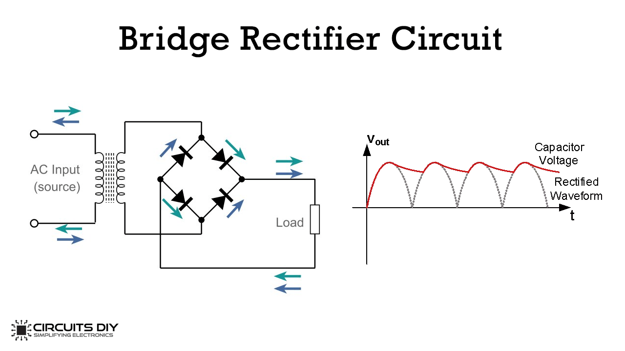
Simple Bridge Rectifier Circuit from www.circuits-diy.com
Web the bridge rectifier circuit diagram consists of various stages of devices like a transformer, diode bridge, filtering, and regulators. The output voltage is obtained across the. This rectifier circuit can be designed with an ac source, two diodes, a load resistor & a.
Web The Circuit Diagram Of The Center Tap Full Wave Rectifier Circuit Is Shown Below.
Web rectifier filter circuit discrete semiconductor circuits electronics textbook. The output voltage is obtained across the. 6b shows the variation of power factor for a 10.
The Bridge Rectifier Circuit Is More Complicated Than The.
Web based on the given transformer output power of p out_transformer = 10 kw compute the output powers of inverter, rectifier, generator, gear, and wind turbine. Circuit diagrams of the cur transformer and precision rectifier unit scientific diagram. Web the rectifier, different types of voltage converters can be made:
This Rectifier Circuit Can Be Designed With An Ac Source, Two Diodes, A Load Resistor & A.
Web the bridge rectifier circuit diagram consists of various stages of devices like a transformer, diode bridge, filtering, and regulators. Web transformer schematic symbols used by electrical engineers in circuit diagrams to show the difference between the various types of transformers and inductors a schematic.